Many if not all of you DIY audio enthusiasts have read about
or have experimented with capacitors in your speaker’s crossover networks each
time noting the audible effects of swapping this out type for that. Changing out standard non-polar electrolytic
capacitors with the same value of an esoteric type (polypropylene, polystyrene,
Teflon, etc.) all alter the way the sonic signature of the speaker sounds. Most or all of you know that adding a small
capacitor in parallel with a larger one again changes the sonic signature, even
when adding them to the Zobel network of a driver (woofer, midrange driver,
etc.). But are these subjective audible effects measurable? Let’s see what I’ve found
out.
Fortunately in my Bozak rebuild project, the crossover
network is mounted on the back of the cabinet making it very easy to perform quick
modifications to it followed up with quick RTA measurements. In doing so, the speaker positions do not
change nor does the microphone position.
With a digital volume control I am assured of the same level of
electrical input and by making back-to-back measurements I am assured of
miniscule environmental influences (temperature, humidity, barometric pressure,
etc.). This removes the possibility of
altering results because of environmental variables and other similar errors
and what I measure is the result of the change, not the result of the change
plus external influences.
My crossover network is a work-in-progress evolving over the
past 19 months to many different approaches, designs, redesigns, and
reworks. Moving to the Peavey RD1.6
tweeter was definitely the right thing to do since it sounds very similar to
the Bozak B-200Y tweeter with none of its HF limitations. Once I got the crossover network “close” to what
I was happy with using the Peavey tweeter, I made before/after measurements
with the only alterations being the addition of 0.1uF non-inductive bypass
capacitors. Below is a picture of the tiny
½” by ½” Xicon polyester non-inductive 100 volt capacitors I chose to use in
this experiment.

0.1uF Non-Inductive Bypass Capacitor
The “before” RTA measurement is below. In other words, this is what the system
measured before the bypass capacitors were added to the crossover network.

I then added this capacitor to all capacitors in the
crossover network (5 total in each speaker).
The “after” RTA measurement is below taken within 20 minutes of the “before”
measurement.

I have no way of super-imposing one measurement on top of another but if you look carefully at the two graphs you will notice some very interesting effects. Let’s break it down and start with the woofer. This woofer uses a first-order Butterworth network and a Zobel so the only change to this part of the network was the additional suppression of undesired HF content to the driver (one bypass capacitor needed here). The yellow vertical line shows the 125Hz point and the green vertical line at the RH side the 450Hz point.
 The measured effects are pretty amazing.
Not only did the VLF content improve (under 125Hz) but also above. What I heard was a smoother and less
emphasized bass response first subjectively perceived as a “loss of bass”
content. Before adding the cap to the
woofer’s Zobel, the bass did have a small peak as noted in the LH picture at
about 200Hz and after the treatment this changed drastically. This huge change influenced what I perceived as
a “loss” but what in effect was an actual “gain” in overall bass content. Everything in the bass region now sounds much
more uniform with fewer peaks and valleys than before making the overall
listening experience one of neutrality.
Deep bass also measured better but I have not listened in depth to the
system’s deep bass response and cannot as yet subjectively comment on its
change.
The measured effects are pretty amazing.
Not only did the VLF content improve (under 125Hz) but also above. What I heard was a smoother and less
emphasized bass response first subjectively perceived as a “loss of bass”
content. Before adding the cap to the
woofer’s Zobel, the bass did have a small peak as noted in the LH picture at
about 200Hz and after the treatment this changed drastically. This huge change influenced what I perceived as
a “loss” but what in effect was an actual “gain” in overall bass content. Everything in the bass region now sounds much
more uniform with fewer peaks and valleys than before making the overall
listening experience one of neutrality.
Deep bass also measured better but I have not listened in depth to the
system’s deep bass response and cannot as yet subjectively comment on its
change.The midrange crossover consists of a second-order Bessel network on both the LPF and HPF sides also using a Zobel network (three bypass capacitors needed here). Band-pass for the midrange driver is 450Hz-2.7KHz as noted by the two green vertical lines. Midrange attenuation is -5.4dB as implemented through a high-precision non-inductive T-pad.

Measured differences in this range are not as drastic as was the woofer’s, however the audible subjective changes were quite noticeable. First, the midrange also appeared smoother as was the woofer, but the contributing “sound” of the bypass capacitor could also be heard. There is now an edginess to the upper midrange that is slightly unnatural but at the same time there is a mellowness to the lower midrange that is extremely appealing. Hollowness in the woodwinds – the bell-sound of a clarinet and the same of an oboe or bassoon – are now very representative of what these instruments actually sound like. Fullness of a trombone is likewise. BUT the first sign of distress occurs in the vocal region where sibilance is over emphasized. Before there was a smoothness to Norah Jones’ voice (Nightingale’s “sing us a song”) where “S” sounds were natural and well controlled. Now there is a slight exaggeration of this region that – well let’s see how the tweeter is affected since this change ripples into the tweeter’s region.
The tweeter uses a second-order Bessel design crossing just above the mathematically-measured point (actual is about 2,800Hz) and the crossover point is indicated by the green vertical line on the LH side of the images. One bypass capacitor is used here. Attenuation is currently -6.69dB using a mixture of non-inductive and inductive resistors in a high-precision T-pad (I am still tweaking the final attenuation level and I may also shift its crossover point). The yellow vertical line is a reference 8KHz point.
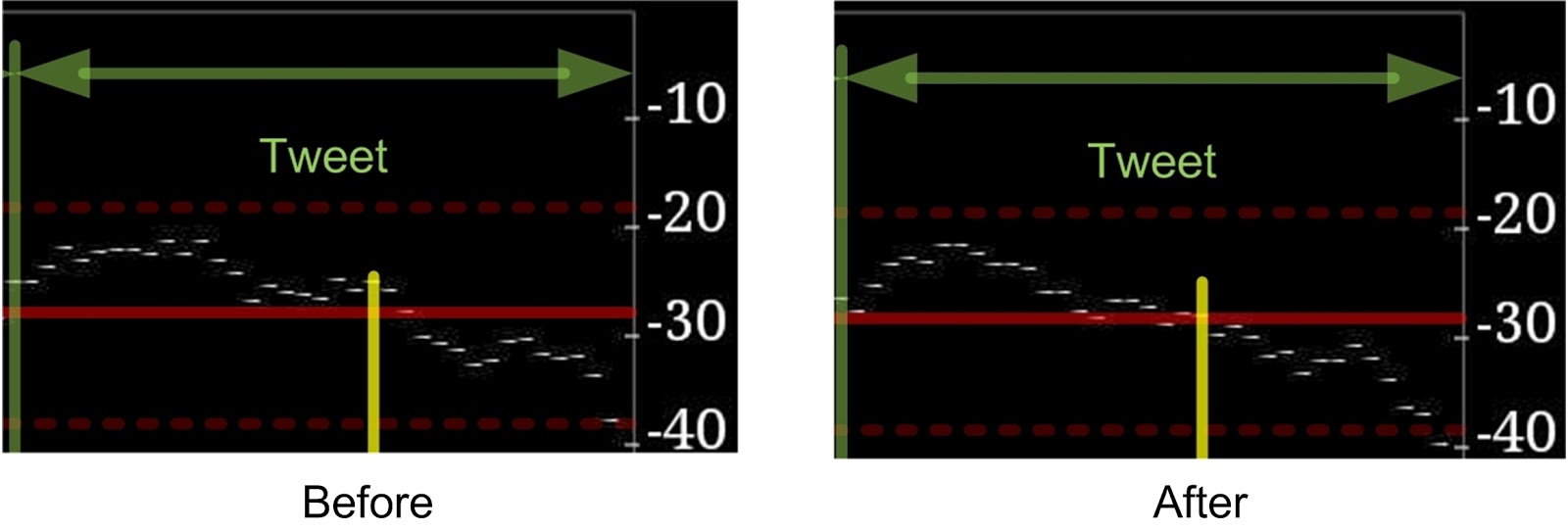
As with the midrange, the measured differences to the tweeter’s response is minor with the greatest impact at the 8KHz point. However, the roll-off is improved just above that point at the expense of a minor over-emphasis in the 4-6KHz (sibilance) region. Subjectively, the sound is duller below 8KHz but slightly brighter above. More very HF content is audible (although still lacking and unbalanced) making it a net positive gain. The sound of this particular capacitor in this region is – well mixed. Like a wishful-sinful, there are some things about this capacitor I really like and some I absolutely hate. Its extension and strain is effortless but its contribution to sibilance makes me want to tear out my hair.
In summary, the subjective effects of a bypass capacitor can be confirmed by objective RTA measurements. The overall sound of my system is greatly improved and I will keep these bypass capacitors in place while waiting for them to burn in. Before swapping them out, I will make another RTA measurement to see if the subjective burn-in effects after 100 hours or so can also be confirmed by objective measurements.
The style of this capacitor (Xicom polyester) is definitely wrong for the midrange and tweeter but satisfactory for the woofer. A good Teflon may do much better but my next venture will be the highly-regarded 0.1uF/160V Vishay MKP1837 (http://www.mouser.com/search/refine.aspx?Msid=61310000&Mkw=MKP1837). Stay tuned for my results in the next round of experiments with bypass capacitors and crossover network tweaks.
I am looking for donations of ultra-high-quality capacitors to complete this experiment. I will need pairs (up to 12) of whatever you wish to send me since I plan to one day change the woofer’s crossover network design from a first-order Butterworth to a second-order Bessel. You can email me at "Philip at OkStateAlumni dot Org" if you wish to help me out in this regard.
Related articles:
The Vishay 1837 Review and Modification
Bypass Capacitors
Mundorf Supreme Capacitor Review - Part 1
Mundorf Supreme Capacitor Review - Part 2
Capacitors: All Things are NOT Created Equal - Part 0
Capacitors: All Things are NOT Created Equal - Part 1
Capacitors: All Things are NOT Created Equal - Part 2
Capacitors: All Things are NOT Created Equal - Part 3
Capacitors: All Things are NOT Created Equal - Part 5
Esoteric Shunt Capacitors - Part 1
Esoteric Shunt Capacitors - Part 2
Esoteric Shunt Capacitors - Part 1
Esoteric Shunt Capacitors - Part 2
Yours for higher fidelity,
Philip Rastocny I do not use ads in this blog to help support my efforts. If you like what you are reading, please remember to reciprocate, My newest title is called Where, oh Where did the Star of Bethlehem Go? It’s an astronomer’s look at what this celestial object may have been, who the "Wise Men" were, and where they came from. Written in an investigative journalism style, it targets one star that has never been considered before and builds a solid case for its candidacy.

Copyright © 2015 by Philip Rastocny. All rights reserved.


